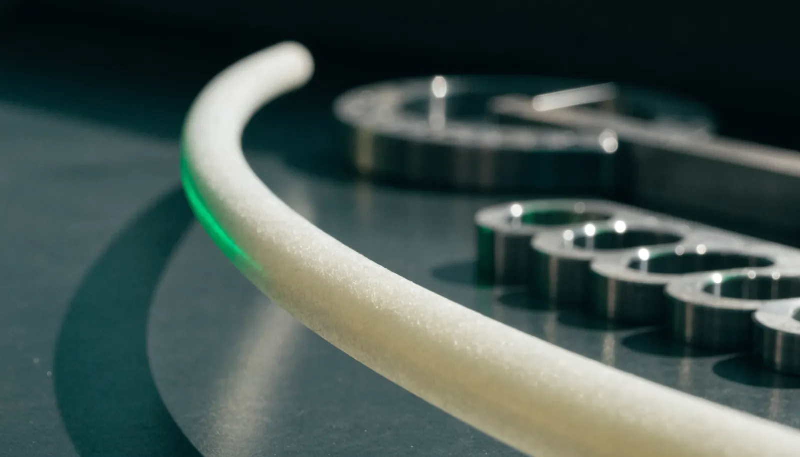
Bend radius represents one of the most critical yet frequently misunderstood parameters in PTFE tubing installation. Engineers routinely calculate pressure ratings and verify chemical compatibility, but improper bending during installation causes premature failure in approximately 30% of PTFE tube applications. Understanding minimum bend radius requirements protects both structural integrity and long-term performance of your fluid transfer system.
Violating minimum bend radius specifications extends beyond immediate kinking. Excessive bending creates stress concentration points that accelerate fatigue, compromise pressure ratings, and create potential leak paths in systems handling aggressive chemicals or high-purity media. For procurement managers specifying PTFE tubing for chemical processing plants or pharmaceutical facilities, proper ptfe tube bending radius specifications must account for outer diameter, wall thickness, material grade, operating temperature, and installation constraints.
Understanding Minimum Bend Radius: Definition and Critical Parameters
Minimum bend radius defines the tightest curve a PTFE tube can sustain without compromising structural integrity or performance. This specification represents the smallest radius measured to the centerline during installation or operation. Unlike flexible elastomeric hoses, PTFE's crystalline molecular structure exhibits limited elastic deformation, making bend radius adherence essential for preventing permanent deformation and stress cracking.
Industry standards typically specify minimum bend radius between 3× and 10× the tube's outer diameter, depending on wall thickness, reinforcement type, and application requirements. A 12mm OD unreinforced PTFE tube with standard wall thickness requires approximately 60-72mm minimum bend radius, while the same diameter with SS316 braided reinforcement may demand 120mm or greater due to the stainless steel's resistance to deformation.
Critical parameters governing ptfe tube bending radius specifications include wall thickness ratio, material crystallinity, and residual stress from manufacturing. Thin-wall PTFE tubing with wall thickness below 0.5mm demonstrates greater flexibility but reduced resistance to collapse under bending loads. The wall thickness to OD ratio directly influences the tube's ability to maintain circular cross-section geometry during bending—ratios below 0.10 typically require larger bend radii to prevent ovalization that restricts flow and creates turbulence.
Material crystallinity affects bend performance through its influence on PTFE's mechanical properties. Virgin-grade PTFE resin processed through precision paste extrusion exhibits crystallinity between 55-75%, with higher crystallinity correlating to increased stiffness and larger minimum bend radius requirements. Reprocessed PTFE often shows reduced crystallinity and inconsistent mechanical properties, making reliable bend radius prediction difficult.
Temperature during installation significantly impacts achievable bend radius. PTFE's glass transition temperature around 19°C marks the point where molecular chain mobility increases substantially. Installing PTFE tubing at temperatures above 25°C allows tighter bending without permanent deformation, while installation below 10°C increases stiffness and raises the practical minimum bend radius by 20-30%.
Bend Radius Calculation: OD, Wall Thickness, and Material Grade
Calculating appropriate bend radius for PTFE tube installations requires systematic evaluation of dimensional parameters and material properties. The baseline calculation begins with outer diameter as the primary variable, then applies correction factors for wall thickness, reinforcement, and application-specific requirements.
The standard formula for unreinforced PTFE tubing establishes minimum bend radius as 6× the outer diameter for general industrial applications. A 6mm OD tube requires 36mm minimum bend radius, while a 25mm OD tube demands 150mm. For applications involving frequent flexing or vibration, increase the multiplier to 8-10× OD to extend fatigue life.
Wall thickness introduces a critical correction factor because it determines the tube's resistance to collapse during bending. Calculate the wall thickness ratio by dividing wall thickness by outer diameter—ratios above 0.15 indicate heavy-wall construction that tolerates tighter bending, while ratios below 0.08 signal thin-wall tubing requiring larger bend radii. A 10mm OD tube with 1.5mm wall (ratio 0.15) may safely bend to 5× OD, whereas the same OD with 0.6mm wall (ratio 0.06) requires 8× OD minimum.
Material grade specifications directly influence bend radius through their effect on mechanical properties. Standard virgin PTFE exhibits tensile strength around 20-35 MPa at room temperature, while modified PTFE compounds incorporating fillers like glass fiber or carbon may show 40-60 MPa. Higher tensile strength materials resist deformation but require larger bend radii—filled PTFE typically demands 8-12× OD compared to 6× for unfilled grades.
Reinforced PTFE constructions with SS304 or SS316 braiding present unique ptfe tube bending radius specifications calculation requirements. The stainless steel braid adds significant bending stiffness, typically increasing minimum bend radius to 10-15× OD depending on braid density and wire diameter. A PTFE stainless steel braided hose with 12mm OD may require 150-180mm bend radius compared to 72mm for unreinforced tube.
Convoluted PTFE hose designs alter bend radius calculations by introducing intentional corrugations that enhance flexibility. Convoluted PTFE constructions typically achieve 3-4× OD minimum bend radius, approximately half that of smooth-bore equivalents. However, the corrugations create surface area for contamination accumulation and complicate cleaning, making them less suitable for high-purity pharmaceutical or semiconductor applications.
Temperature and Pressure Effects on Bending Performance
Operating temperature profoundly influences PTFE tube bending performance through its effect on material properties and dimensional stability. PTFE exhibits a complex relationship between temperature and mechanical strength, with critical transition points at 19°C (glass transition), 30°C (crystalline transition), and 327°C (melting point).
At cryogenic temperatures approaching -200°C, PTFE maintains flexibility and impact resistance. However, the material's elastic modulus increases substantially—approximately 2.5× higher at -196°C compared to room temperature. This stiffness increase effectively raises the minimum bend radius by 40-60% for installations involving liquid nitrogen, liquid oxygen, or other cryogenic media. A tube requiring 60mm bend radius at 20°C may demand 90mm at -180°C to prevent stress cracking during thermal cycling.
Elevated temperatures between 100-200°C reduce PTFE's mechanical strength and elastic modulus. At 150°C, PTFE's tensile strength drops to approximately 60% of room temperature values, while its tendency toward cold flow increases dramatically. Tubes bent near minimum radius at elevated temperatures may gradually deform over weeks or months, eventually kinking or developing stress cracks. For high-temperature applications, increase the bend radius multiplier from 6× to 8-10× OD.
Pressure effects on bend radius primarily manifest through hoop stress interaction with bending stress. A pressurized tube experiences circumferential stress proportional to pressure and diameter, following the relationship σ = PD/2t where P represents pressure, D is diameter, and t is wall thickness. For tubes operating above 50 bar (725 psi), increase minimum bend radius by 25-50% depending on pressure rating utilization.
The interaction between temperature and pressure creates particularly challenging conditions for ptfe tube bending radius specifications. A tube rated for 300 psi at 20°C may only safely handle 75 psi at 200°C due to reduced material strength. Calculate the effective bend radius as: Rmin = (6 × OD) × (Tfactor) × (Pfactor), where Tfactor accounts for temperature effects (1.0 at 20°C, 1.5 at 150°C) and P_factor reflects pressure utilization (1.0 at 0 bar, 1.5 at maximum rated pressure).
Dynamic bending applications involving vibration or repeated flexing require additional safety factors. For installations subject to vibration from pumps, compressors, or process equipment, specify minimum bend radius at 12-15× OD to limit stress amplitude and extend fatigue life. Static dissipative PTFE formulations used in volatile media applications may show different fatigue characteristics due to conductive filler effects on crack propagation.
Installation Best Practices and Failure Prevention
Proper installation techniques prevent the majority of bend radius-related failures in PTFE tubing systems. Even correctly specified tubes fail prematurely when installation practices violate minimum bend radius requirements or introduce stress concentrations through improper support and routing.
Pre-installation planning begins with accurate measurement and routing design. Map the complete tube path including all bends, offsets, and connection points before cutting tube to length. Calculate the minimum bend radius for each direction change and verify adequate clearance exists. For complex installations, create a full-scale template using flexible wire or rope to validate routing feasibility before committing expensive PTFE tubing.
Support spacing directly impacts bend radius maintenance over time. Unsupported tube spans sag under their own weight plus fluid load, creating unintended bends that may violate minimum radius specifications. Install supports at intervals not exceeding 1 meter for tubes up to 12mm OD, 0.75 meters for 12-25mm OD, and 0.5 meters for larger diameters.
Never force PTFE tubing into tight bends by pulling or levering—the material's limited elastic recovery means overstressed tubes retain permanent deformation. For manual bending, support the tube on both sides of the intended bend point and apply gradual, even pressure. Purpose-built tube bending tools with radius guides ensure consistent results and prevent localized kinking.
For installations in cold environments below 15°C, warm the tubing to 25-30°C using heat guns or warm water baths before bending. This temporary softening allows tighter bending without exceeding stress limits. Avoid installing PTFE tubing in direct sunlight or near heat sources above 40°C, as excessive softening may cause the tube to deform under its own weight.
Maintain straight tube sections of at least 3× OD length before and after fittings to prevent stress concentration at the fitting-tube interface. This straight section allows the tube to develop its natural bend radius without forcing sharp transitions that concentrate stress.
Measure actual installed bend radii using radius gauges or flexible measuring tools, documenting any locations approaching minimum specifications. Check for ovalization—if the tube cross-section shows more than 10% deviation from circular, the bend radius is insufficient and requires correction. Look for whitening or stress marks on the tube exterior, which indicate overstressing that compromises long-term reliability.
Advanced Fluro Private Limited provides comprehensive technical support for PTFE tube installation planning and failure analysis. Our ISO 9001:2015 certified manufacturing processes ensure consistent material properties that enable reliable bend radius prediction. For applications requiring custom dimensions or specialized formulations, our engineering team calculates application-specific ptfe tube bending radius specifications accounting for your operating conditions, spatial constraints, and performance requirements.
Understanding and implementing proper ptfe tube bending radius specifications protects system integrity, prevents premature failures, and ensures long-term performance in demanding chemical processing, pharmaceutical, and industrial applications. For detailed specifications on our precision-manufactured PTFE products, visit our technical blog or explore our product range to find solutions matching your exact requirements.

Article by
AFTubes Team
Savio Pereira is a Chemical Engineer who has held leadership roles in companies like IBM. A passionate problem solver who thrives at finding solutions to engineering and business problems alike using simple innovative ideas. He believes in doing things differently rather than doing different things. His vision is to make Advanced Fluro (P) Ltd the most valuable company in the fluouro polymer industry.